GATE10V/div
VCC10V/div
OUT10V/div
I
IN
5A/div
-
-
TIMER
1 V/div
I
IN
0.5 A/div
GATE 10 V/div
OUT 10 V/div
-
-
TPS2490
TPS2491
www.ti.com
SLVS503D NOVEMBER 2003REVISED JULY 2012
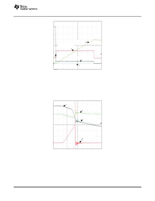
Figure 15. Current Limit Overview
The TPS2490/91 responds rapidly to the short circuit as seen in Figure 16. The falling OUT voltage is the result
of M1 and C
O
currents through the shorts impedance at this time scale. The internal GATE clamp causes the
GATE voltage to follow the output voltage down and subsequently limits the negative V
DS
to 12 V. The rapidly
rising fault current overdrives the GATE amplifier causing it to overshoot and rapidly turn M1 off by sinking
current to ground. M1 slowly turns back on as the GATE amplifier recovers; M1 then settles to an equilibrium
operating point determined by the power limiting circuit.
Figure 16. Current Limit Onset
Minimal input voltage overshoot appears in Figure 16 because a local 100-糉 bypass capacitor and very short
input leads were used. The input voltage would overshoot as the input current abruptly drops in a typical
application due to the stored energy in the input distributions inductance. The exact waveforms seen in an
application depend upon many factors including parasitics of the voltage distribution, circuit layout, and the short
itself.
Copyright ?20032012, Texas Instruments Incorporated
13
发布紧急采购,3分钟左右您将得到回复。
相关PDF资料
W83772G
IC H/W MONITOR 8-TSSOP
W83L786G
IC H/W MONITOR 28-SSOP
X96011V14IZ
IC SENSOR TEMP BIAS SGL 14-TSSOP
XR4151CP-F
IC CONV VF/FV 8PDIP
XRP7714ILB-0X14-F
IC REG 5OUT BCK/LINEAR 40TQFN
XRP7740ILB-0X18-F
IC REG 5OUT BCK/LINEAR 40TQFN
XRP7740ILBTR-F
IC REG 5OUT BCK/LINEAR 40TQFN
ZDS1009TA
IC CURRENT MIRROR SOT223-8
相关代理商/技术参数
TPS2491DGSR
功能描述:热插拔功率分布 Retry Pos Hi-Voltage Pwr-Limiting RoHS:否 制造商:Texas Instruments 产品:Controllers & Switches 电流限制: 电源电压-最大:7 V 电源电压-最小:- 0.3 V 工作温度范围: 功率耗散: 安装风格:SMD/SMT 封装 / 箱体:MSOP-8 封装:Tube
TPS2491DGSRG4
功能描述:热插拔功率分布 Retry Pos Hi-Voltage Pwr-Limiting RoHS:否 制造商:Texas Instruments 产品:Controllers & Switches 电流限制: 电源电压-最大:7 V 电源电压-最小:- 0.3 V 工作温度范围: 功率耗散: 安装风格:SMD/SMT 封装 / 箱体:MSOP-8 封装:Tube
TPS2491EVM-002
功能描述:电源管理IC开发工具 TPS2491-002 Eval Mod RoHS:否 制造商:Maxim Integrated 产品:Evaluation Kits 类型:Battery Management 工具用于评估:MAX17710GB 输入电压: 输出电压:1.8 V
TPS2492EVM-001
功能描述:电源管理IC开发工具 TPS2492 Hot Swap Controller Eval Mod RoHS:否 制造商:Maxim Integrated 产品:Evaluation Kits 类型:Battery Management 工具用于评估:MAX17710GB 输入电压: 输出电压:1.8 V
TPS2492EVM-003
功能描述:电源管理IC开发工具 TPS2492 Hot Swap Controller Eval Mod RoHS:否 制造商:Maxim Integrated 产品:Evaluation Kits 类型:Battery Management 工具用于评估:MAX17710GB 输入电压: 输出电压:1.8 V
TPS2492PW
功能描述:热插拔功率分布 Pos Hi-Vltg Pwr-Ltd Hotswap Controller RoHS:否 制造商:Texas Instruments 产品:Controllers & Switches 电流限制: 电源电压-最大:7 V 电源电压-最小:- 0.3 V 工作温度范围: 功率耗散: 安装风格:SMD/SMT 封装 / 箱体:MSOP-8 封装:Tube
TPS2492PW
制造商:Texas Instruments 功能描述:HOT SWAP CONTROLLER IC 80V TSSOP-14
TPS2492PWR
功能描述:热插拔功率分布 Pos Hi-Vltg Pwr-Ltd Hotswap Controller RoHS:否 制造商:Texas Instruments 产品:Controllers & Switches 电流限制: 电源电压-最大:7 V 电源电压-最小:- 0.3 V 工作温度范围: 功率耗散: 安装风格:SMD/SMT 封装 / 箱体:MSOP-8 封装:Tube
